Frame Design of Engine Mount
Overview
Frame construction is used throughout the aerospace industry in the creation of welded steel-tube fuselages, piston-engine motor mounts, ribs, and landing gear. In this activity I design a frame assembly for a motor mount structure for a Lycoming O-300 to be installed in a light aircraft.
Equipment
Computer with Autodesk® Inventor® installed and access to the internet.
Procedure
The frame must meet the constraints shown below.
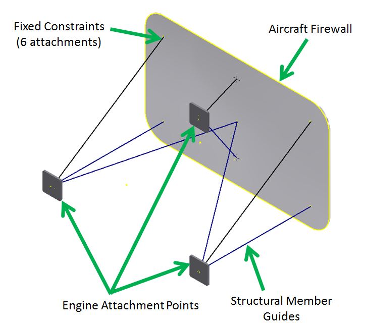
- The large plate represents the aircraft firewall as shown in the image below. This must be grounded as the stable part of the frame. Use fixed constraints on the six firewall to structural member attachment point.
- The structure will support one Lycoming O-300 engine (250 lb) attached at the three points indicated.
- The structure will be loaded with negative 3 G and positive 6 G which is simulated by exaggerated engine weight.
- The structural members will be 1 ½ in. ANSI pipe.
- Frame members should be mitered as necessary
Calculated Forces
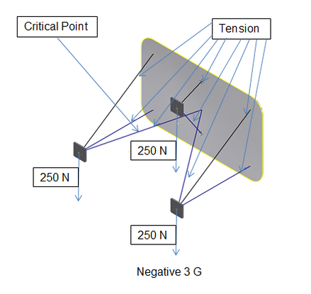
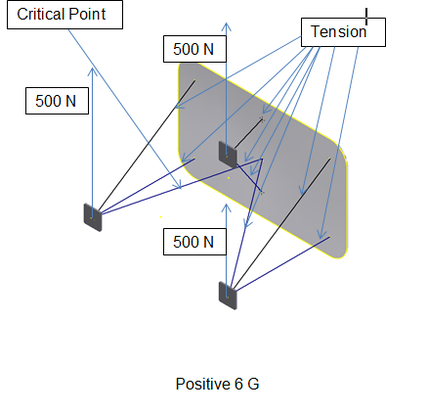
I calculated the forces that must be simulated with the positive and negative G loads. I labeled the frames below with the forces for each loading condition. I also labeled the structural members below as compression or tension. I predicted where the critical point will be for each loading condition.
|
|
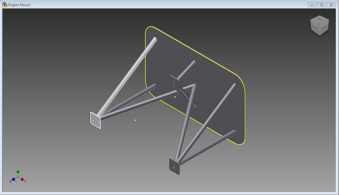
Design
I used Autodesk Inventor to create a model of the frame design that met the constraints above.
Frame Analysis
The yellow arrows are a 250N force down. Each black dot represents a pinned constraint. The eight solid lines are the structural members.
Before 7th Constraint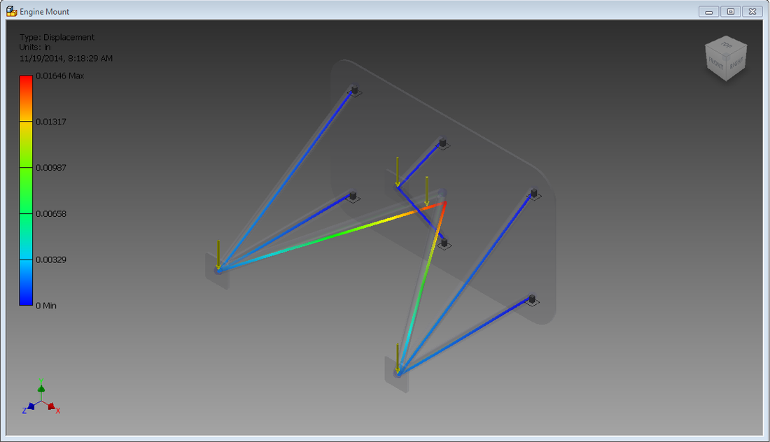
|
After 7th Constraint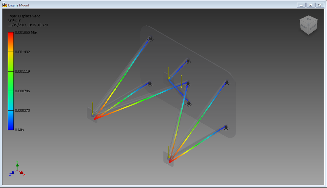
|
Negative 3 G's
The yellow arrows are a 500N force up. Each black dot represents a pinned constraint. The eight solid lines are the structural members.
Before 7th Constraint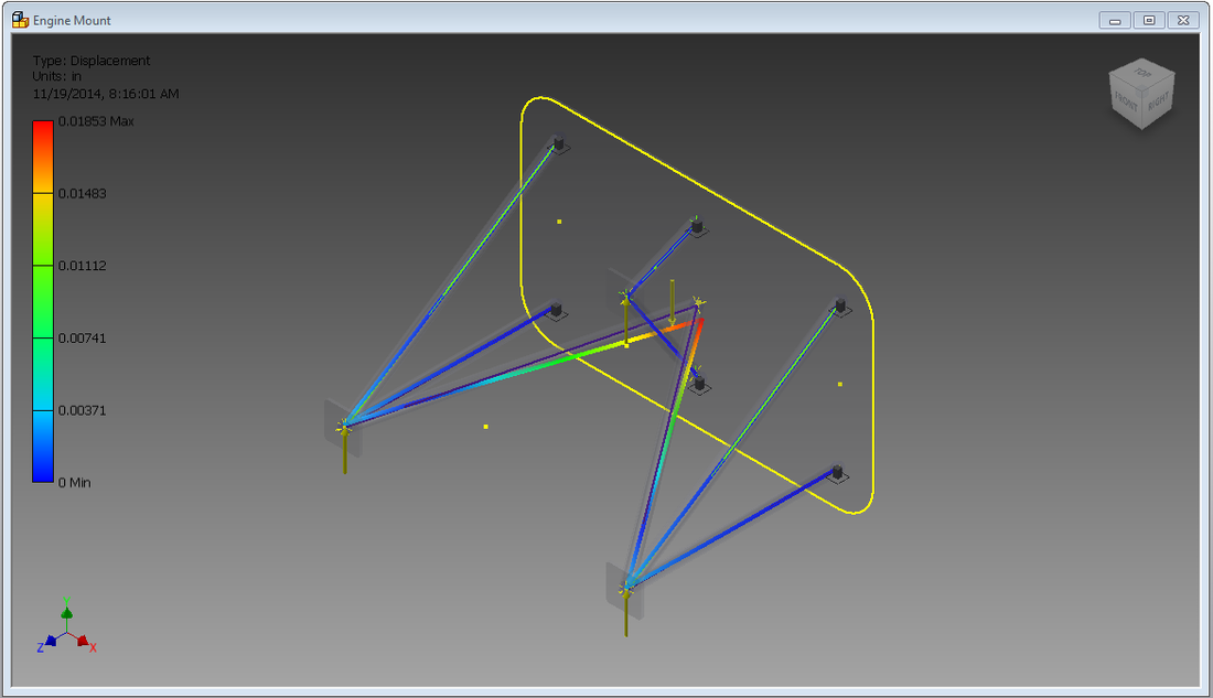
|
After 7th Constraint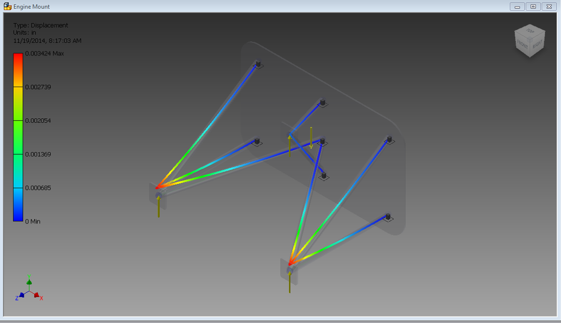
|
Positive 6 G's
Mass and price of materials needed to produce the frame design.
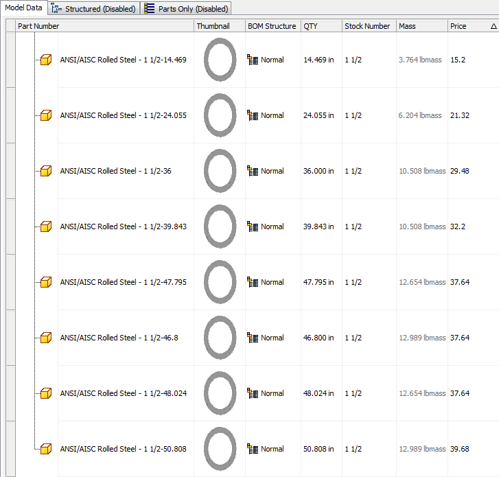
Cost supplied by MetalsDepot
Design Benefits
What makes my design unique is the added fixed constraint on the original firewall. The design only calls for six fixed constraints, but a seventh fixed constraint makes the forces on the engine only apply near the engine instead of applying all over the structural members. Also, the actual frame design is made of ANSI extra-strength pipe which is stronger than regular steel pipe.
Conclusion
1. Explain how the frame analysis showed that the critical area was different than the critical area that you predicted.
The frame analysis showed that the critical area was at the tips of the structural members. I predicted that the critical area was in the middle. The frame analysis showed that the critical area wasn't where i expected it to be.
2. Explain what additional loading conditions that an aircraft designer needs to include as a constraint.
The aircraft designer needs to include the seventh fixed constraint on the firewall. If he does, the forces will only act on the ends of the structural members instead of all over them.
